- Parametric
Modeling
in Design
Centre
Pompidou-Metz
Objectives:
This
project is an attempt to create a parametric model for Centre Pompidou-Matz.
The
author tries to manipulate the original design based on her design intents using
the Rhino-Grasshopper
platform.
•Challenges
in this project was parametric modeling of building
components
included:
–Shell Shape Parametric Design
–Building Height
–Shell Pattern
–Openings’ size and orientation
Introduction
The Centre
Pompidou-Metz is a museum of modern and contemporary arts located in Metz,
with 5,000 m2 (54,000 sq ft) divided between 3 galleries, a
theatre, and an auditorium. The first piece of the building designed by
Japanese architect Shigeru Ban in 2006 in a 12,000 m2 site. The roof
structure of this building has a remarkable design inspired by a Chinese hat found
in Paris By Shigeru Ban (Figure 01). The building mass has two main components: a large hexagon structured roof, and a central
spire (Figure 02).
Figure 1-https://www.centrepompidou-metz.fr/en/roofing
Figure 02-https://www.area-arch.it/en/centre-pompidou-metz/
The central piece reaches 77
meters and holds three rectangular galleries in different orientations that extending
out over the roof with big picture windows angled towards landmarks (Figure 03).
Ceiling heights are different in three galleries and riding progressively from
a height of 5.7 m on the first floor to 18 m on the upper floor.
Figure 03-https://www.area-arch.it/en/centre-pompidou-metz/
The roof is one of the most complex structures of the time: a
90 m (300 ft) wide hexagon covering the building's floor map, with a surface area of 8,000 m2 (86,000 sq ft) which is composed of glue
laminated timber with wooden beams spaced 2.90
meters apart in a hexagonal pattern. This mesh enables the roof to span approximately 40 meters (Figure 04) and
to makes the roof a self-supporting element, resting on only a few supporting
parts(Figure 05).
Figure 04-https://www.area-arch.it/en/centre-pompidou-metz/
Figure 05- https://inspiration.detail.de/centre-pompidou-metz-103525.html?lang=en
The roof’s geometry is irregular, featuring
curves and counter-curves over the entire building (Figure 06). Moreover, a white fiberglass membrane and a
coating of Teflon cover the
entire wooden structure to protect it from direct sunlight, while providing a
transparent view at night (Figure 07).
Figure 06-https://balmondstudio.tumblr.com/post/104833243773
Figure 07-https://www.area-arch.it/en/centre-pompidou-metz/
Every single beam was CNC-machined to unique
proportions (Figure 08). This precise approach enabled both the production of multi-directional
curves and the perforations for the final assembly (node points, pins, and
braces). In February 2009, a metal ring and cone-shaped section were assembled
to the top of the roof to support the roof (Figure 09).
Figure 08- Ref: Researchgate
Figure 09-ref:https://www.pinterest.com/pin/324118504403558790/?lp=true
Appendix:
 |
Figure 10- Site Plan-Figure 3-https://www.area-arch.it/wp-content/uploads/sites/6/2015/07/Untitled-76.jpg
|
 |
Figure 11- First Floor Plan- Ref:https://www.area-arch.it/en/centre-pompidou-metz/
 |
Figure 13- Third Floor Plan- Ref: https://www.area-arch.it/en/centre-pompidou-metz/
|
 |
Figure 15- Section 01- Ref: https://www.area-arch.it/en/centre-pompidou-metz/
Modeling
in
Rhino
•Drawing
floor plans in Rhino using PolyLine
Figure 17-Drawing Floor plans in Rhino
•Application
of
NURBS
curve
in drawing of basic
geometry makes
final result a parametric model, and enables further modification on it.
Figure
18 -Drawing Roof Boundary in Rhino
Modeling in Grasshopper
Creating parametric
model of building’s floors in GH
 |
| Figure 19 - GH Baked Model representation in Rhino |
 |
Figure 20-Modeling central spire in Grasshopper: “Height” is a variable
|
•Creating
a 2D Pattern- based on Penrose alorithm- for
Roof Shell in GH
 |
Figure 21- Application of Penrose Pattern on roof projection on a flat surface
•Creating
a 2D Pattern- based on Penrose algorithm- for Roof Shell in GH

|
| Figure 22- Penrose Pattern representation on flat surface in Rhino |
|
Figure 23- Trimming Penrose Pattern to place it inside the hexagone
|
•Creating
a Roof Openings in GH- Need to bake the geometry for later subtract application
Figure 24- Creation of Roof openings in GH

|
Figure 25- Baking
Roof openings
•Creating
parametric columns using point input in GH
Figure 26- Creating
parametric builing columns
Figure 27- Test
if column parameters work properly
•Creating
3D Model for Roof Shell using NURBS
curve in GH-
Figure 28-Roof
mesh representation in Rhino
•Mesh
Difference and Mesh Union application to create a 3D model for roof shell in
GH-
Figure 29- Roof
Shell
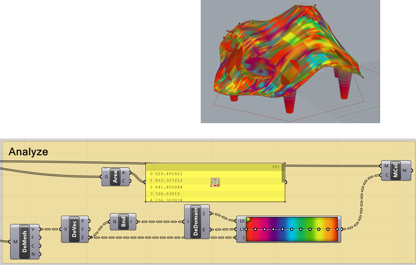
Analyze
in
Grasshopper
•Application
of “mesh colors” to analyze vertices of the generated mesh
•Application of “Area”
to
calculate mass area
Figure 30- Analyze
of Vertices and area
Generative
Modeling in
Grasshopper
•Application
of “Kangaroo Physics” and “WeaverBird”
using primary mesh model to create
the physically-based model.
•Application
of “Kangaroo Physics” and “WeaverBird”
using primary mesh model to create
the physically-based model.
Figure 31- create the physically-based model
•Application
of “Project” to project previous created 2D Penrose pattern on roof mesh.
 Figure 32- Projection of Penrose pattern
from a flat surface on 3D model of roof Figure 32- Projection of Penrose pattern
from a flat surface on 3D model of roof
Application
of “Pipe” to create beam structure of roof
Figure 33-Creating roof beams using “Pipe”
Baking Final 3D Model
|
|